2. On-site Calibration
2.1. On-site Settings
The On-site settings are enabled by swithing on the On Site Switch.
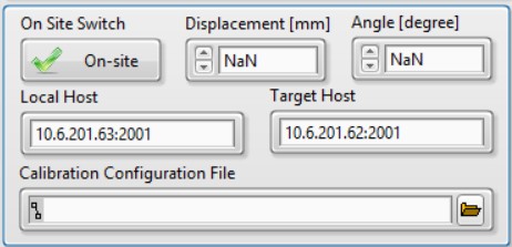
Displacement: Change the distance of the rotational mirror to the beam expansion part.Angle: Change the angle of the rotational mirror.Local Host: The IP and port for the local UDP service.Target Host: The IP and port of the remote second pulse generator.Calibration Configuration File: The automatic calibration script.
Note
When Displacement and Angle have the value of NaN, the rotational mirror will stay in the current position.
2.2. Calibration Configuration File
The calibration file holds a list of job setups. Each line is treated as a job. The job paramerters are separated by comma in the following definations:
Date Time, Duration [s], Displacement [mm], Angle [degree]
Below is an example of the configuration file.
2024-11-23 10:20, 10, 10, 10
2024-11-25 15:59, 10, 10, 10
2024-11-25 16:01, 20, 0, 0
2024-11-25 16:03, 30, 10, 30
2.3. Calibration Procedure
2.3.1. Hardware Preparation
Connect the hot source and heat it up.
Connect the cables of the step motors to the step motor controller’s corresponding DB9 sockets.
The DB9 socket in the main FTS part should be connected to
X.The DB9 socket of the linear step motor in the beam reflection part should be connected to
Y.The DB9 socket of the rotational step motor in the beam reflection part should be connected to
Z.
Connect the COM port of the step motor controller to the PC’s COM port or use a USB-to-COM cable for transformation.
Make sure the step motor controller is in
Remotemode.Connect the socket of LE in the main FTS part to the DAQ box.
Connect the USB cable of the DAQ box to the PC.
Connect the second pulse generator to the PC with network cable.
Connect the trigger and pulse cable of the second pulse generator to the DAQ box.
2.3.2. Manual Calibration
The following procedures are used to perform a single calibration manually.
Open the application
FTS.exe.Select and set
SM Controller.Select
Reciprocatingmode.Set
Loop Number.Change
Max Posto adjust spectra resolution.Confirm
Linear Encoder Nameis valid and withctr0selected.Switch on
On Site Switch.Change mirror positons by setting
DisplacementandAngle.Select
Trigger Sourceif you want the job is fired by the second pulse generator.Fill
Data File SuffixandCommentson needs.Click
Start.
2.3.3. Automatic Calibration
The procedures are generally similar to Manual Calibration but with the Calibration Configuration File being set.
Open the application
FTS.exe.Select and set
SM Controller.Select
Reciprocatingmode.Change
Max Posto adjust spectra resolution.Confirm
Linear Encoder Nameis valid and withctr0selected.Switch on
On Site Switch.Select the
Calibration Configuration File.Select
Trigger Source.Fill
Data File SuffixandCommentson needs.Click
Start.
Note
Loop Number is no long valid, since the job is stopped by Duration in the calibration configuration file.